
The short answer: if a remote works well on the bench and becomes unreliable after installation, check the receiver antenna before you increase transmitter power or replace the radio. In practice, antenna length, nearby metal, cable routing and mounting position decide the usable range more often than the number printed on the product page.
I have seen the same receiver cover 150 metres in an open test and struggle across a small workshop once it was bolted inside a steel cabinet. Nothing was wrong with the encoder or the RF chip. The antenna had simply been turned into part of the wiring loom and then shut behind a metal door.
Start with electrical length, not a convenient piece of wire
A straight wire antenna is normally cut for a fraction of the radio wavelength. A quarter-wave is a useful reference: about 23.8 cm at 315 MHz, 17.3 cm at 433 MHz, 8.6 cm at 868 MHz and 8.2 cm at 915 MHz in free space.
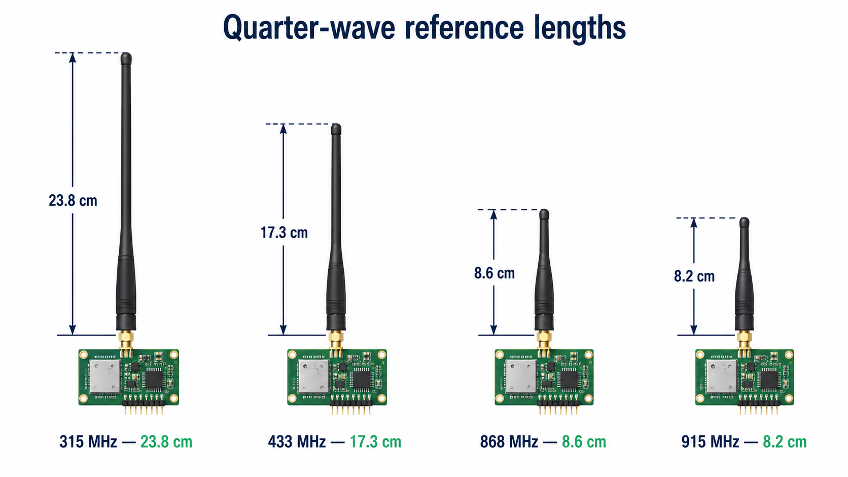
Quarter-wave reference lengths are useful starting points; the final antenna still needs to suit the receiver board and enclosure.
Those figures are starting points, not permission to replace every antenna with wire cut to that length. A PCB antenna, helical spring or loaded whip may be deliberately shorter. The receiver board, ground area, enclosure and matching network all affect the final tuning. If the supplier provides a tested antenna, use it as supplied unless you can measure the result.
One common field mistake is to shorten a 433 MHz wire because it is untidy, or coil the extra length beside the relay. The receiver may still work at close range, so the mistake survives commissioning. The margin disappears later when the battery gets weak, a vehicle changes position or electrical noise rises.
A metal enclosure changes the job completely
A radio antenna inside a closed steel box is not “protected”; it is screened. A small gap around the door may leak enough signal for a bench demonstration, but the result will vary badly with direction and distance. An aluminium enclosure can create the same problem.
If the receiver must live in a metal cabinet, bring the antenna outside. The clean method is a proper RF connector or a short coaxial feed to an external antenna. Keep the coax feed as feed line and the exposed antenna as the radiating section. Do not simply join a long random wire to the existing antenna pad and route it through the cabinet. The extra wire becomes part of the antenna and usually changes the tuning.
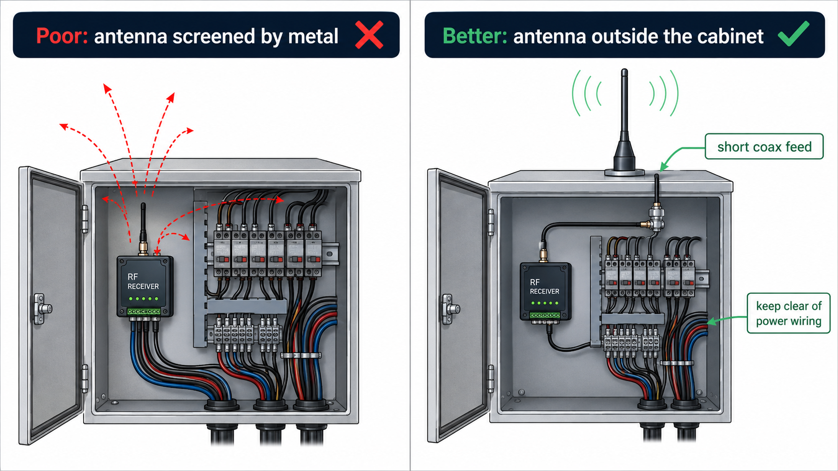
Inside a metal cabinet, use a short coaxial feed to move the radiating antenna outside and away from power wiring.
For plastic enclosures, the material is normally less troublesome, but do not assume every plastic cover is invisible to RF. Carbon-filled plastics, metallic paint, foil labels and a large battery pack close to the antenna can reduce performance.
Give the antenna some empty space
The last few centimetres around the antenna matter. I try to keep a wire or whip away from large metal surfaces, relay bodies, transformers, switching power supplies and bundled machine cables. As a practical first pass, leave 30–50 mm of clearance where the enclosure allows it. More space is useful around a low-power receiver.
Route the antenna away from motor leads and contactor wiring. Do not cable-tie it tightly to the DC supply harness. A harness can detune the antenna, carry switching noise and change position every time the machine is serviced. All three make a fault difficult to repeat.
Also keep the antenna reasonably straight. A gentle bend is usually less damaging than folding it back on itself or making a tight coil. If the design needs a compact antenna, choose a tested helical or PCB antenna rather than improvising one during assembly.
Orientation matters, but real operators do not hold remotes perfectly
A straight transmitting antenna and a straight receiving antenna couple best when their polarization is similar. If the receiver antenna is vertical and the operator normally holds the remote upright, the link is usually more consistent. Turn one antenna through 90 degrees and the signal can drop sharply, especially in open space.
Do not design around one ideal hand position. Operators turn remotes sideways, put them in pockets and use them from different sides of a machine. Install the receiver antenna in the orientation that works across the expected approaches, then test the weak directions. A small position change often helps more than chasing a perfect theoretical angle.
The ground side is part of the antenna system
A quarter-wave whip does not work alone. It uses the receiver ground or another conductive surface as its return path. A module that performs well on a large development board may lose range on a small final PCB because the available ground area changed.
With an external coaxial antenna, the centre conductor carries the RF signal and the shield provides the reference. Poor connector contact, a broken shield or a crushed coax can produce intermittent range faults that look like interference. Check the connector mechanically before changing software settings.
A field test that tells you something useful
Do not judge the installation by one successful button press. Use a repeatable test:
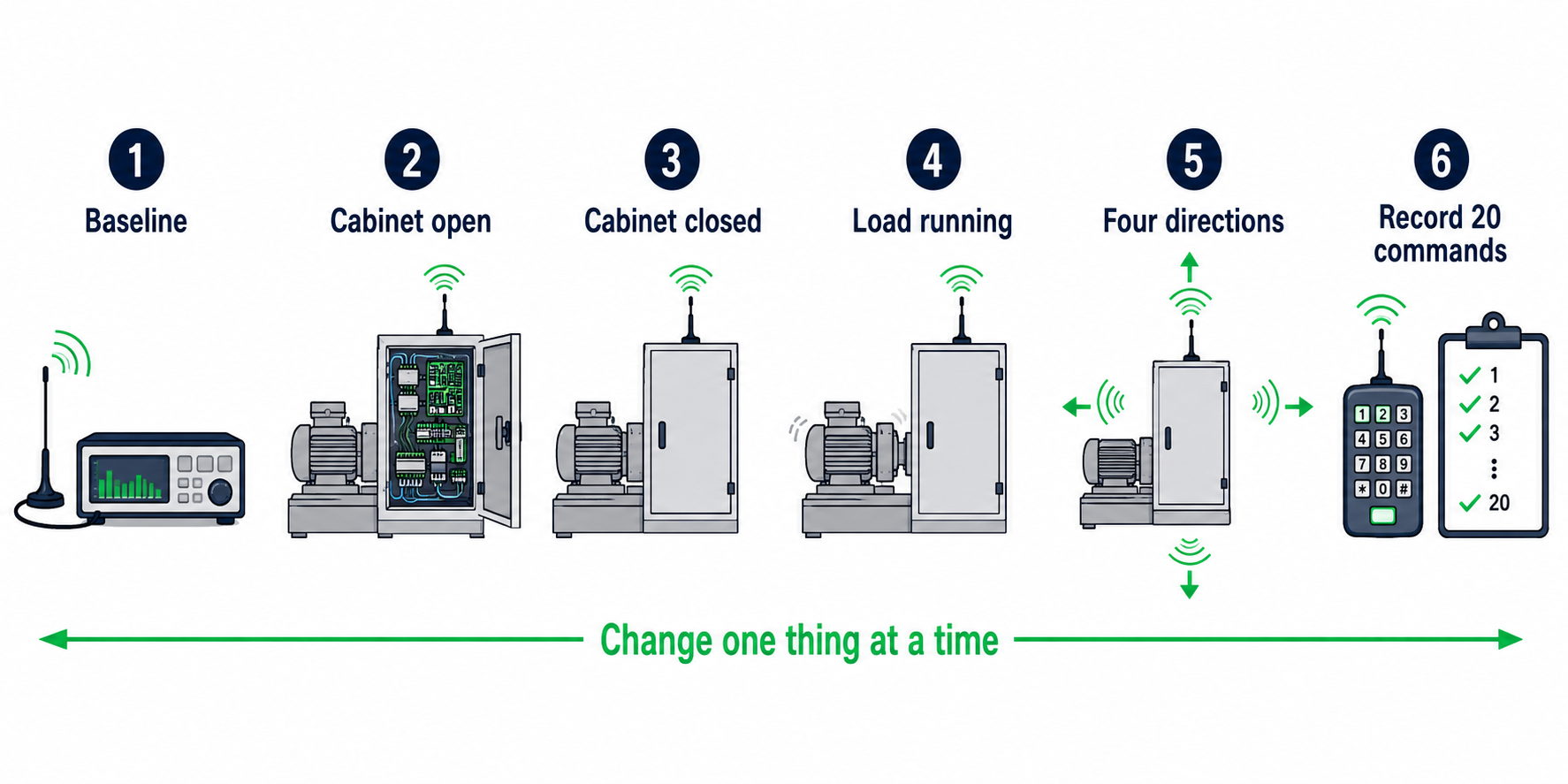
Keep the path and operating conditions repeatable, and change only one installation variable at a time.
Confirm a baseline with the receiver powered on the bench and the specified antenna fitted.
Install the receiver but leave the cabinet open. Test from the intended operating points.
Close the cabinet and repeat the same path. A large drop points directly at enclosure or antenna placement.
Run the motor, pump, contactor or lighting load. If performance changes only under load, investigate conducted and radiated noise as well.
Test from at least four directions and with the remote held as an operator would actually use it.
Send 20 commands at each difficult point and record missed or delayed responses. One lucky command proves very little.
Repeat with a battery near the replacement threshold, not only with a fresh cell.
When moving the antenna, change one thing at a time. Shifting it 50 mm, rotating it or moving it outside the box can be enough to identify the cause. If you change the antenna, power supply and receiver together, you may get a working machine without learning what failed.
When an external antenna is worth the extra hardware
Use an external antenna when the receiver sits inside metal, the operating point is close to the range limit, the machine blocks the line of sight, or reliable coverage is required around several sides of a large structure. It is also sensible when the receiver must be mounted low but the antenna can be placed higher.
Choose the antenna for the actual frequency and connector, keep the coax no longer than necessary and seal outdoor feed-throughs against water. For moving equipment, add strain relief. A good antenna with a damaged cable is still a poor antenna.
Before you ask for more transmit power
More power is not the first repair. It can increase battery drain, regulatory risk and interference while leaving the receiving installation unchanged. First verify the frequency, antenna type, placement, supply quality and noise under load. Only then decide whether the application genuinely needs a higher-link-budget system.
The useful question is not “How many metres is this remote?” It is “How much link margin remains after the receiver is installed in the real machine?” Antenna work is where that margin is most often won or lost.