
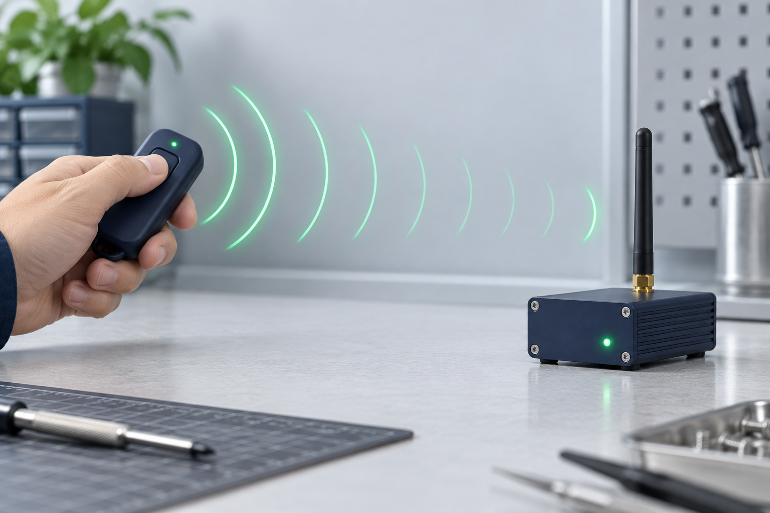
A receiver marked −110 dBm can decode a very weak signal—but only under the test conditions behind that number. It is not a promise that the remote will work at a certain distance. When someone sends me a sensitivity figure without the data rate and error-rate condition, I treat it as half a specification.
What the negative number says
dBm is a power level measured against one milliwatt. In receiver specifications the numbers are usually negative because the signal arriving at the receiver is tiny. A threshold of −110 dBm is weaker than −100 dBm, so, with the same test method, the −110 dBm receiver can still decode a signal that the −100 dBm receiver may lose.
A 10 dB difference is a tenfold difference in signal power at the receiver input. It is not ten times the operating distance. Walls, the operator's hand, antenna orientation, cable loss and reflections do not scale in such a tidy way.
Ask what the radio had to decode
Sensitivity is normally quoted at a defined data rate, modulation, receiver bandwidth, packet length and error rate. Change those settings and the same radio can produce a very different number. For a concrete example, the CC1101 data sheet lists −116 dBm at 0.6 kBaud and −104 dBm at 38.4 kBaud in its 433 MHz receive specifications. Those are test points for a chip, not range claims for a finished remote system.
This is why I do not rank two modules by the bold dBm number on their product pages. I want to know the settings and the required packet success rate. A figure measured with a slow test packet cannot be compared fairly with one measured at a faster rate or a stricter error target.
The useful number is the margin you have left
Suppose a receiver needs −110 dBm and you measure −92 dBm at its antenna input at the hardest operating point. That is 18 dB above the threshold. Now imagine the final enclosure, cabling and hand position remove 12 dB. You have only 6 dB left. The arithmetic is simple; obtaining a representative measurement is the hard part.
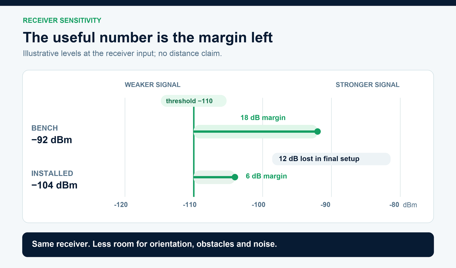
At the quoted sensitivity threshold, some packets are already failing at the stated test error rate. A control system needs room above that edge for people walking between antennas, a machine moving, a battery ageing and nearby equipment switching on. I would rather see a modest radio specification with measured margin in the installed machine than a spectacular bench figure with none.
A good sensitivity figure cannot fix a noisy site
The receiver also has to distinguish the wanted signal from other signals and electrical noise. A nearby transmitter or a noisy motor drive may reduce command reliability even while the remote's signal looks strong. Signal-strength readings can include unwanted energy; they do not prove the receiver decoded the right packet.
When a link fails, separate three observations: is RF energy reaching the antenna, are valid packets being decoded, and is the receiver accepting the command? Those are different stages. Swapping in a “more sensitive” receiver will not repair a wrong code format or a poor antenna location.
What I check before approving a module
Ask for sensitivity with its frequency, modulation, data rate, bandwidth and packet or bit error condition.
Compare candidate modules under the same settings, including selectivity or blocking data if other radios are nearby.
Test with the final antenna and enclosure, at the worst operator positions and orientations.
Count accepted commands, not just LED flashes or signal-strength peaks, while the actual machine is running.
Record the distance and conditions where misses begin, then move the receiver or antenna before asking for more transmitter power.
If the supplier cannot give every radio parameter, a repeatable installed test is still possible. Agree on the operating positions and a command success target, then run the same test for each candidate. The result tells you more about your machine than a bare −110 dBm line ever will.