
The relay clicks, but the machine does nothing. In most cases, that means the radio command reached the receiver and the receiver decided to operate the output. It does not prove that current passed through the relay contact, that the machine input saw a valid signal, or that the machine was permitted to move.
This is one of those faults that becomes expensive when people keep working on the wireless side. I have watched antennas, batteries and complete receiver boards get replaced while an open common wire sat two terminals away. Once you hear a clean, repeatable click, move your test point downstream.
What the click actually proves
A relay click proves only a short part of the control chain. The transmitter sent something the receiver accepted, the receiver logic energized the relay coil, and the armature moved far enough to make a sound.
It does not prove that COM changed from NC to NO. It does not prove that a terminal screw is gripping the conductor. It does not prove that the PLC input common is correct. It does not prove that a contactor coil has enough voltage to pull in. Treat the click as a useful dividing line, not as proof that the output is healthy.
Start by checking whether the machine can run locally
Before measuring the receiver, operate the machine from its original pushbutton, pendant or local control. Confirm that the emergency stop is reset, guards and limit switches are satisfied, the drive is ready, and the machine is in the correct local/remote mode.
This step matters because the wireless receiver cannot override a missing safety permissive. If the local control also fails, stop troubleshooting the RF system. The fault is in the machine, its power, or its interlock chain.
For low-voltage control inputs, one useful test is to remove the receiver from the circuit and briefly operate the two machine-input terminals exactly as the original pushbutton would. Do this only when the wiring diagram confirms that it is a safe low-voltage contact input. If that test runs the machine, the downstream logic is available and the problem is between those terminals and the receiver output.
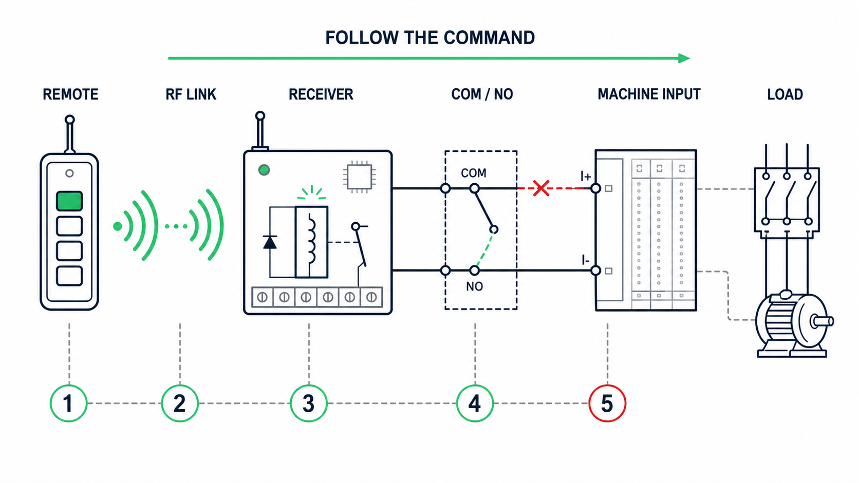
Find the first point that does not change
Work in one direction and watch the indicators that already exist:
Remote button or transmit indicator
Receiver valid-command indicator
Relay click or output LED
PLC input, drive input or controller input LED
Contactor, solenoid or actuator response
The first point that fails to change is where the useful diagnosis starts. If the PLC input LED turns on but the contactor does not, the receiver has done its job. If the relay clicks but the PLC input LED stays dark, stay with the contact wiring and input reference.
I often record one button press on a phone when the indicators are not visible at the same time. A short video is better than two people calling out what they think happened.
Check COM and NO with power removed
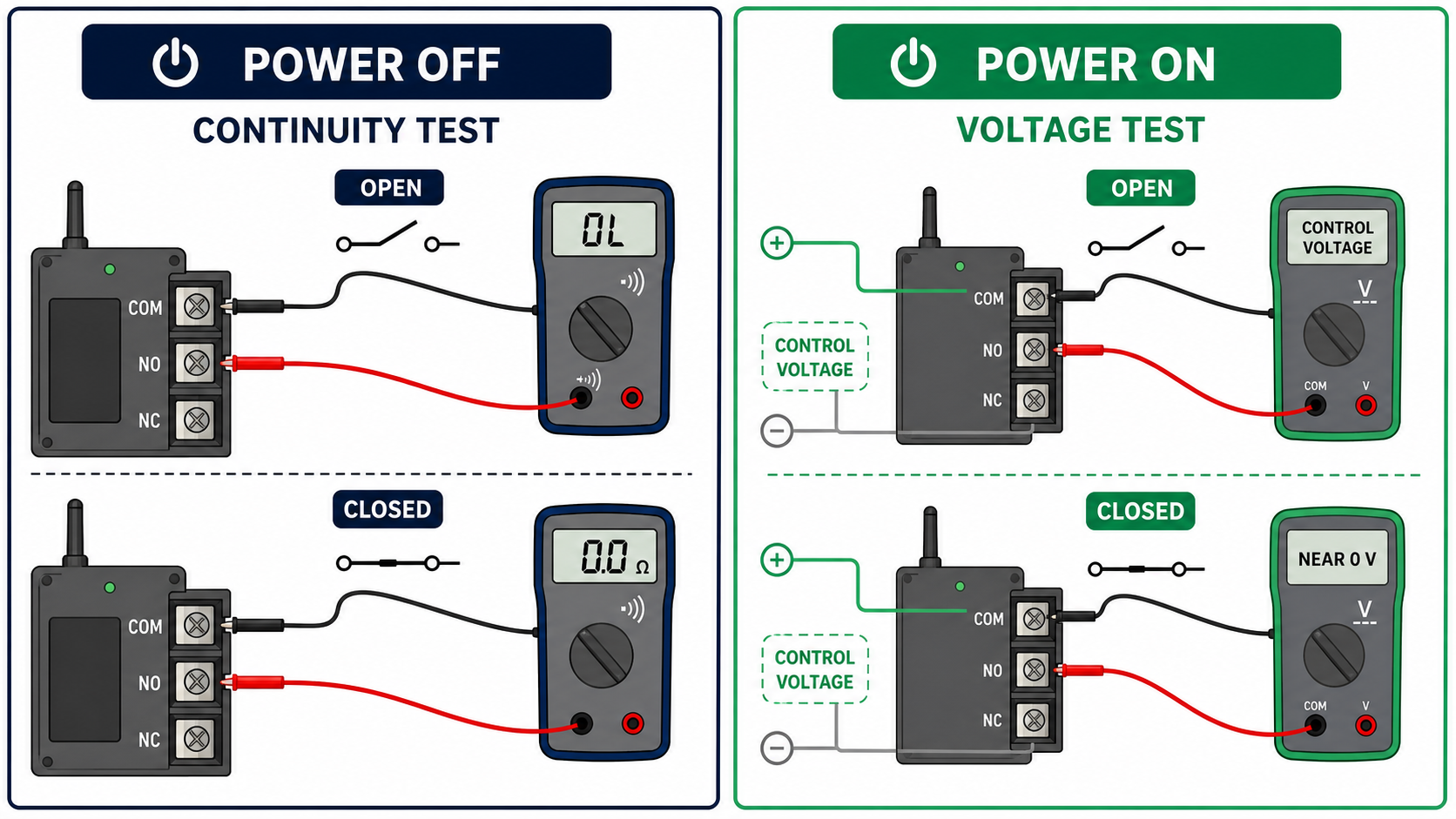
Disconnect power and isolate the output from the machine before using continuity mode. Measure directly across COM and NO. With the channel off, the circuit should be open. With the channel commanded on, it should close consistently.
Do not rely only on the meter beep. Note the resistance if your meter can show it. A healthy small relay contact and sound terminal connection should normally be very low resistance. A reading that jumps, stays at several ohms, or changes when the wire is moved points to a damaged contact, loose terminal, broken conductor or poor crimp.
Also check the terminal labels against the exact board. On crowded terminal blocks, installers often land one wire on NC or on the supply negative beside COM. The relay still clicks, so the mistake looks more complicated than it is.
A dry contact needs a complete circuit
A dry relay contact supplies no voltage of its own. COM and NO are simply the two sides of a switch. The machine must provide the control voltage and the return path.
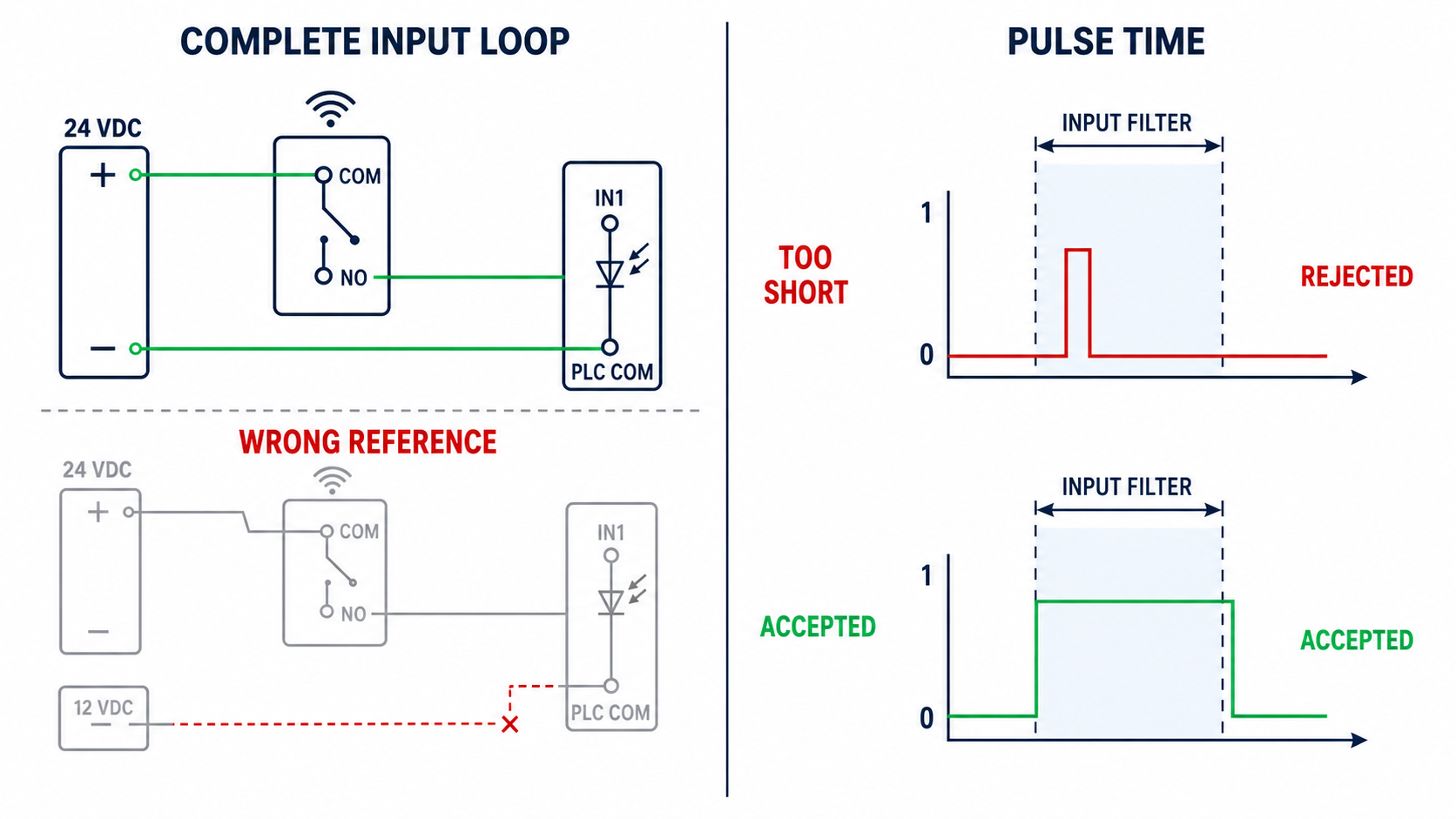
For a controller input that expects a button closure, the usual connection is the controller's button common to relay COM and the trigger input to relay NO. For a PLC input, the correct arrangement depends on whether the input group is sourcing or sinking. The input terminal and its common must belong to the same input circuit.
This is where I see many neat-looking installations fail. The receiver is powered from a convenient 12 V supply, the PLC input uses 24 V, and somebody assumes the two negatives must be joined. Sometimes that defeats the relay isolation; sometimes the PLC still has no valid reference. Follow the PLC input diagram rather than trying combinations.
Measure the machine input while the relay is on
Continuity with power removed is only half the test. Reconnect the circuit, use the correct voltage range, and measure at the machine input while commanding the receiver.
For a voltage-sensing input, measure between the input terminal and its specified common. The reading should cross the input's stated on-threshold and remain there long enough to be recognized. Measuring from the input to a random chassis screw can give a believable but useless number.
For a contact-closure input, measure the voltage across COM and NO. When the relay is open, you may see the machine's control voltage across the contacts. When the relay closes, the voltage across the contacts should fall close to zero. If several volts remain across a supposedly closed contact, inspect the relay, terminal block and wiring joints.
One field trap is an unloaded voltage that disappears under load. A weak supply, damaged trace or high-resistance joint can show the expected voltage on a digital meter but collapse as soon as a contactor coil or interface relay is connected. Measure with the real load connected whenever it is safe to do so.
Make sure the pulse is long enough
Some receivers are set to momentary mode but produce a pulse that is too short for the machine input filter. A PLC may scan the input after the pulse has already ended. A gate controller may require a deliberate contact closure rather than a very quick edge.
Increase the momentary time within the machine manufacturer's allowed range and test again. In many ordinary control circuits, a few hundred milliseconds is easier for the input to recognize than a brief pulse, but there is no universal correct setting. A hold-to-run function, a start command and a door-trigger input all need different behavior.
Also confirm that the receiver is not in toggle mode when the machine expects a pulse. Toggle mode leaves the contact on after the first press and off after the next. On an edge-triggered controller, that can make every second press appear dead.
Listen for a contactor that tries but cannot pull in
A small receiver relay may close correctly while the device it drives only hums, chatters or remains still. Measure the voltage directly across the contactor or solenoid coil during the command.
Low coil voltage can come from an undersized power supply, a long cable, a poor return connection or too much voltage drop across the relay contact. DC coils also need correct polarity when a flyback diode or electronic economizer is fitted. AC and DC coil versions may look identical from the outside, so read the coil label.
If the receiver output is being asked to switch a motor or large solenoid directly, stop and check the actual load. The printed relay current is not a promise that the assembled receiver can handle motor inrush. Use the receiver to drive a correctly rated interposing relay or contactor when required.
Do not bypass the machine's decision
The input can turn on and the machine can still refuse to move. At that point, look at the machine logic: emergency-stop circuit, overload relay, pressure switch, travel limit, guard switch, drive fault, mode selector and software permissives.
On PLC-controlled equipment, monitor the command input and the internal permission bit separately if you have access. A live input with a false permission tells you exactly why changing the receiver will achieve nothing.
Never bridge a safety input just to prove that the RF command works. Test the normal command path and let the safety system remain in control.
A ten-minute field sequence
prove that the local control operates the machine.
confirm that the receiver output LED and relay respond every time at close range.
isolate power and check COM-to-NO continuity in both output states.
reconnect the machine and measure the correct input voltage relative to its own common.
compare the configured output mode and pulse time with what the machine expects.
measure coil voltage under load if a contactor or solenoid is involved.
check the machine permissives if its input changes but motion does not begin.
Keep the order. Each test removes one section of the system from suspicion. Randomly moving wires usually creates a second fault before the first one is understood.
What to send when you need support
A clear support request should include the receiver model, supply voltage, output mode, a photo of the terminal labels, the machine input wiring diagram, and three measurements: voltage at the receiver supply during operation, voltage at the machine input when commanded, and resistance across COM and NO with power removed.
Also say whether the original local control still works and whether the machine input indicator changes. Those details are more useful than “the relay clicks but nothing happens,” and they usually allow an engineer to identify the next test without guessing.
The practical rule
Once a receiver relay clicks reliably, stop treating the problem as radio range until evidence sends you back there. Prove the contact, prove the circuit reference, prove the input duration, and then prove the machine permission.
Wireless control is only one link in the chain. A good diagnosis follows the command all the way to the load and stops at the first place it disappears.