
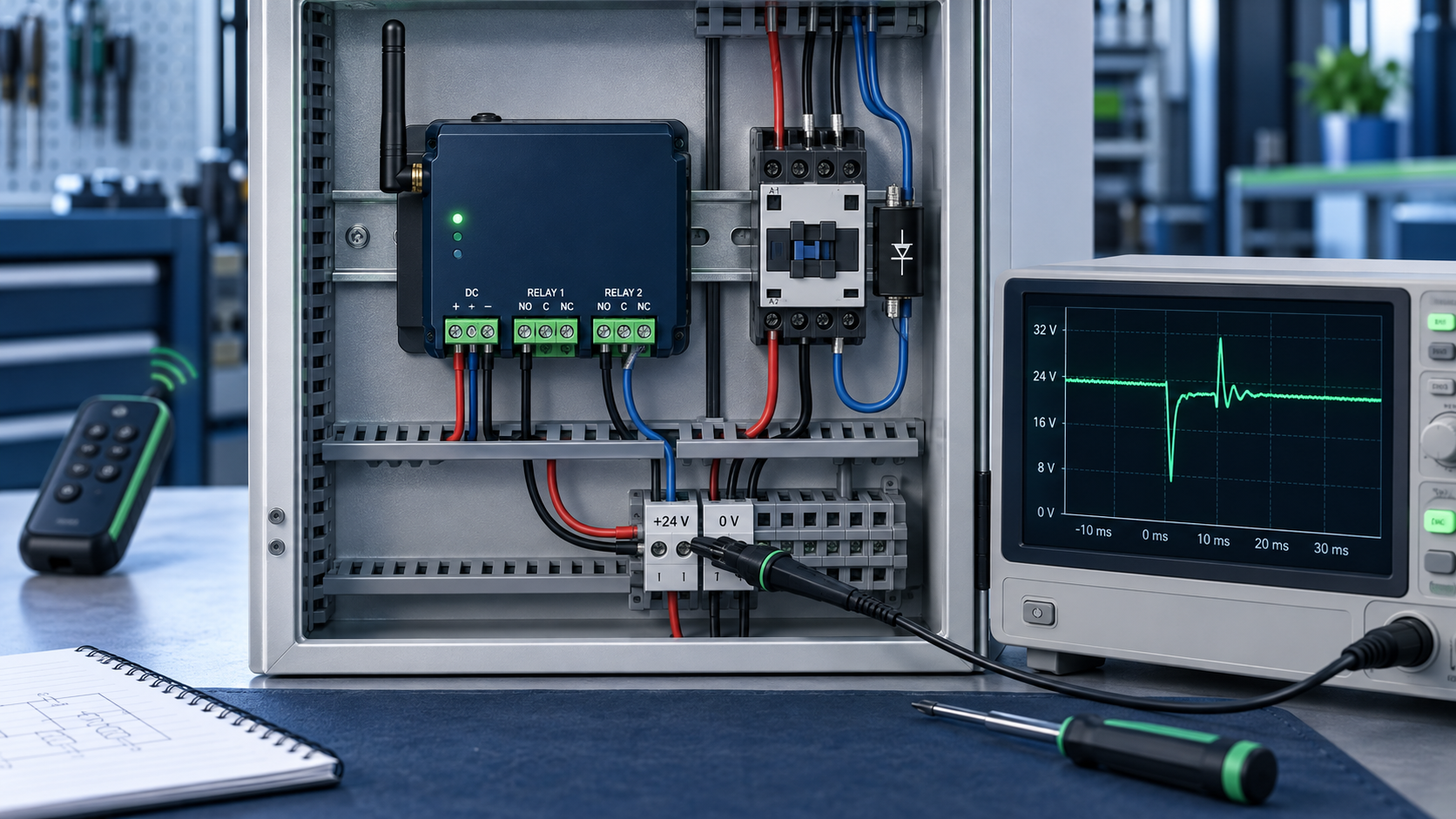
If the receiver works with no load connected but resets, drops out, or becomes unreliable as soon as a motor, solenoid valve, contactor, or lamp is switched, start on the power side—not the radio side. In most cases the receiver is seeing a supply dip, an inductive voltage spike, or a burst of electrical noise through the wiring. Changing the antenna may change the symptom, but it rarely fixes the cause.
What the symptom is telling you
Watch the receiver before moving any wires. The timing of the failure is useful evidence.
If the power LED goes dark and comes back, even briefly, suspect a supply dip or a poor return path.
If the relay chatters or releases while the button is still held, check receiver voltage under load and the control mode before blaming RF range.
If the problem appears when the load turns on, look for inrush current and shared supply wiring.
If it appears when the load turns off, inductive flyback is the stronger suspect.
If range collapses only while a motor is running, conducted or radiated noise may be desensitizing the receiver.
A digital multimeter can miss a dip that lasts only a few milliseconds. The receiver's LED or relay sound often gives the first clue; an oscilloscope across the receiver power terminals gives the answer.
Start with one isolation test
Disconnect the load from the receiver output, but leave the receiver powered and paired. Operate the remote several times.
If the receiver is now stable, the radio link, pairing, and basic receiver logic are probably fine. Reconnect the load through a separate, correctly rated power source or an intermediate contactor and test again. This two-step test saves more time than changing remotes, antennas, or frequencies at random.
If the receiver still resets with no load connected, then check its input voltage, polarity, antenna position, and local interference. Do not continue adding suppression parts to a load that is no longer in the circuit.
The three faults I find most often
1. The receiver and load share an undersized supply
A label that says “12 V” does not tell you how stiff the 12 V rail is. A valve coil, brake, contactor, or small motor may pull several times its running current at the moment it energizes. Thin cable, a long cable run, a tired battery, or a low-cost adapter can let the voltage at the receiver fall below its reset threshold.
Measure at the receiver terminals, not at the power supply. Those are two different points once current starts flowing. Also check the negative return. I have seen a perfectly good positive feed blamed when the real voltage was being lost in one shared ground wire.
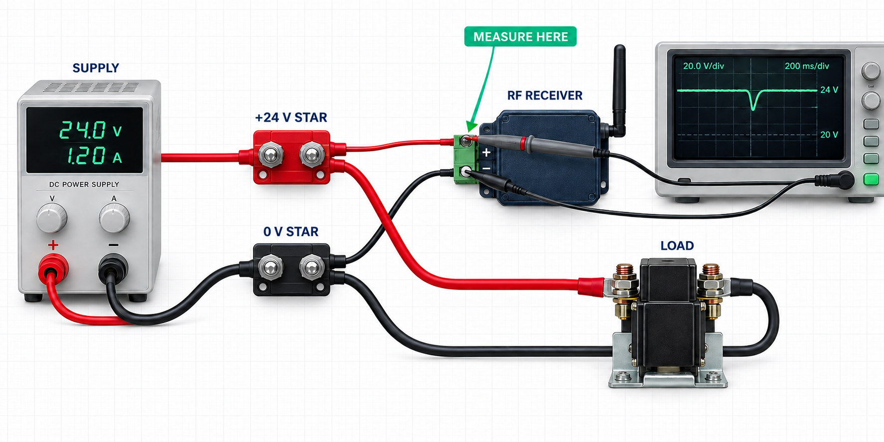
For a quick proof, power the receiver from a separate regulated supply while keeping the output contacts isolated from that supply. If the fault disappears, redesign the power distribution rather than masking it in software.
2. The inductive load has no suppression
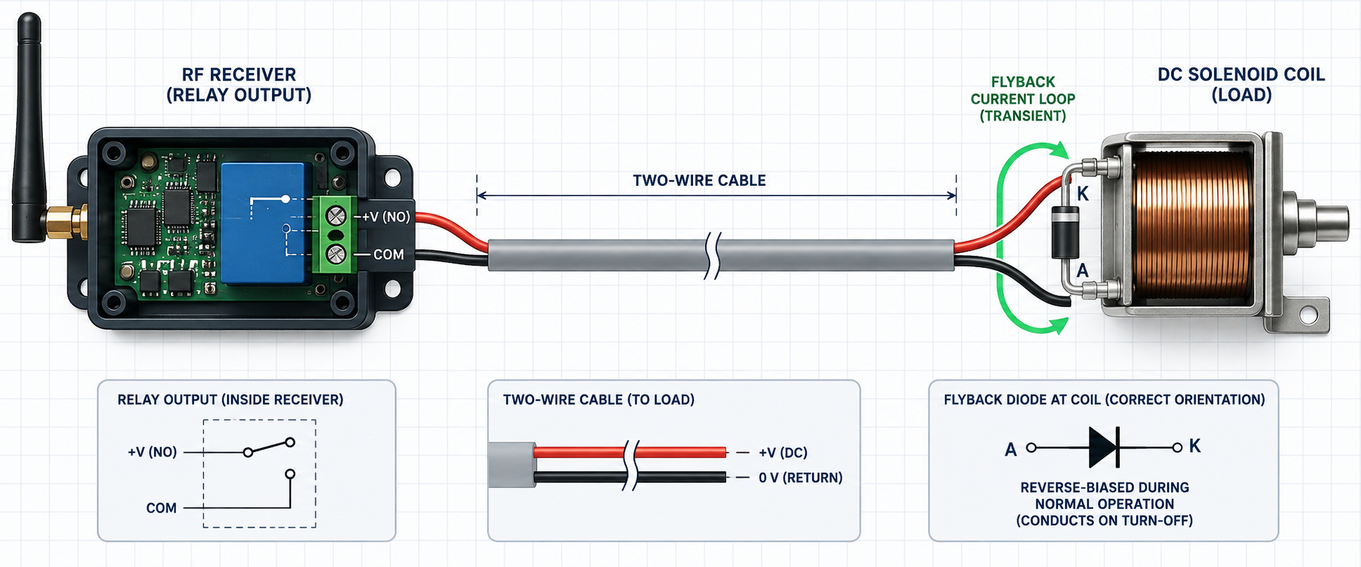
When current through a coil is interrupted, the magnetic field collapses and the coil produces whatever voltage it needs to keep current flowing. That voltage can arc across relay contacts, couple into nearby wiring, or travel back through the supply.
For a DC coil, a flyback diode across the coil is the usual starting point. Fit it physically close to the coil and observe polarity: the diode must be reverse-biased during normal operation. Be aware that a simple diode slows current decay, so a valve or contactor may release slightly later.
Where fast release matters, a correctly rated TVS diode or a diode-plus-zener arrangement may be a better choice. For an AC coil, use a properly rated RC snubber or MOV specified for the coil and supply voltage. A DC flyback diode must not be placed across an AC coil.
The suppressor belongs at the noise source. A device fitted beside the receiver can leave the entire cable between receiver and load acting as an antenna.
3. Load current shares the receiver's wiring path
Even with a large power supply, poor wiring can create ground bounce. If motor or coil current returns through the same thin conductor used by the receiver, every current step changes the receiver's local reference voltage.
Run the receiver supply and the load supply back to a solid distribution point. Keep high-current motor leads away from the antenna and RF section. Twist supply-and-return pairs where practical, and avoid large cable loops. For brushed motors, suppression at the motor terminals is usually more effective than adding parts at the receiver.
A practical test sequence
Test the receiver unloaded. Confirm repeated commands are stable with the output disconnected.
Listen and watch. Note whether the failure happens on energizing, during running, or on release.
Measure at the receiver. Check voltage during both button press and release. Use an oscilloscope if the LED flickers but the meter looks normal.
Separate the supplies. Temporarily use a known-good regulated supply for the receiver.
Add the correct suppression at the load. Select a diode, TVS, RC snubber, or MOV according to load type and release-time requirements.
Correct the current paths. Shorten high-current wiring, improve the return conductor, and separate it from the antenna.
Retest at the worst condition. Use low battery voltage, a cold coil, the longest cable, and repeated switching—not just one successful press on the bench.
Choose the suppression device by the load
DC relay, solenoid, or contactor coil: flyback diode for simple, low-cost suppression; TVS when faster release is important.
AC coil: rated RC snubber or MOV. Confirm leakage current is acceptable for the control circuit.
Brushed DC motor: suppression at the motor, short motor wiring, and often a separate motor power path.
Large motor or heater switched by a contactor: let the RF receiver drive the contactor coil, not the main load. Suppress the coil as well.
Always size suppression parts for the actual working voltage and stored energy. If the load manufacturer specifies a suppression network, use that recommendation first.
What does not fix the root cause
Replacing the antenna before checking whether the receiver is rebooting.
Choosing a relay with a larger resistive current number while ignoring motor inrush and contact arcing.
Adding a very large capacitor across the receiver supply without measuring the dip or checking startup current.
Fitting the suppressor at the control cabinet when the noisy coil is several metres away.
Connecting extra ground wires without understanding where the load current will return.
A local capacitor can help a clean but slightly soft supply ride through a brief dip. It should be the final correction after the cable, supply capacity, and transient source are understood—not the first guess.
Before the machine ships
Operate every inductive load repeatedly while commanding the receiver. Test with the antenna in its final position and the enclosure closed. Check the lowest expected supply voltage, not only a fully charged bench supply. If the machine has several coils, test the worst simultaneous combination.
I also mark the suppression device on the wiring diagram. Otherwise it has a habit of disappearing during a later valve, contactor, or harness replacement, and the “RF problem” returns six months later.
The short engineering conclusion
When a wireless receiver fails exactly as a load switches, treat the RF section as innocent until the unloaded test proves otherwise. First stabilize the voltage at the receiver, then control the transient at the load, and finally tidy the current paths and cable routing. Once those three are right, the radio link usually behaves exactly as it did on the bench.