
One wireless remote can command two linear actuators, but it does not, by itself, keep them in sync. If the actuators support the same frame, lid or platform, use a compatible synchronization controller with position feedback, or a mechanical arrangement designed to keep both sides together. Two relays switching at the same time only solve the starting command.
The first question I would ask is simple: are these two independent movements, or two supports carrying one load? Two separate vents may only need to open together. Two pushrods lifting the ends of one rigid frame need a much closer look at what happens between the start and the end of the stroke.
“Both moving” is a poor test of synchronization
Put two unloaded actuators on a bench, connect them to one command and they may look well matched. Install them on a frame with more weight on one side and the result can change. Load, friction, alignment, temperature and voltage drop can affect the travel speeds. The same model number and the same power supply do not establish a position tolerance.
Here is an illustrative calculation, not a product test. Suppose actuator A travels at 25 mm/s and B at 24 mm/s. Starting from the same position, after ten seconds A has travelled 250 mm and B 240 mm. The mismatch is 10 mm. Neither actuator has to fail for the frame to become uneven.
Reducing the radio starting delay will not remove that continuing speed difference. Even if both outputs energize at exactly the same instant, the position error can keep growing while they run. Progressive Automations explains this same distinction in its guide to actuator synchronization: a common switch does not compensate for unequal operating conditions.
Ask what the supplier means by “synchronized”
In a wireless switch description, the word can mean several things:
Two receiver outputs respond to the same button.
A remote output follows the ON/OFF state of a wired input.
Several drives maintain a specified relationship between their measured positions.
Those are different functions. Before treating a wireless kit as a motion synchronizer, ask where it measures actuator position, how it corrects a mismatch and what error limit it guarantees under the stated load. If there is no position measurement or designed mechanical coupling, do not assume the system can correct travel drift.
A longer radio range, more relay channels or a faster receiver does not answer those questions. They may improve the command interface, but they do not tell the controller which side of the frame is getting ahead.
Keep the wireless command upstream of the motion controller
A practical arrangement is to let the radio receiver request UP, DOWN or STOP from the synchronization controller. That controller reads both actuators and adjusts their individual drives. The position comparison stays in the motion system rather than being inferred from whether two receiver LEDs are lit.
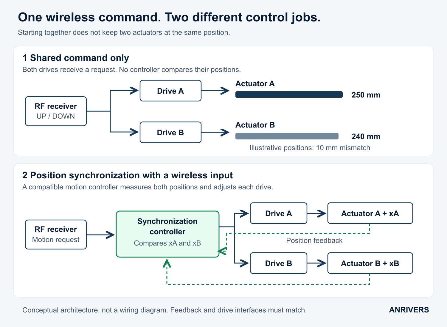
Conceptual control architecture, not a terminal wiring diagram. The upper positions illustrate the calculation above; they are not measured product results.
The controller may be a separate control box or built into compatible smart actuators. For example, Thomson describes smart actuators exchanging position and speed information and adjusting motion as the load changes. That capability comes from the actuator control system, not from a shared remote button.
Hall sensors, encoders and potentiometers are common feedback options, but the interface must match the controller. Check signal voltage, resolution, direction sensing and the reference procedure. With incremental feedback, two equal pulse counts are only useful if both positions have a valid reference and the counts are correctly converted into travel.
End switches do not keep the frame level halfway up
An end switch tells the system that one actuator has reached a travel boundary. It does not measure the difference between the two sides during the rest of the stroke.
If one side reaches its limit first, allowing the other side to continue may increase the twist in the frame. Define the group response in the controller. Do not rely on both built-in limits eventually opening, and do not use the frame's stiffness as the method of keeping the actuators together.
Some matched systems use a documented reference or initialization cycle. Follow that procedure. Driving two arbitrary actuators against their end stops is not a universal way to calibrate them.
The important fault is one side stopping alone
For actuators carrying a shared rigid load, ask what happens if one drive faults, one feedback signal becomes invalid or one side reaches a limit early. Continuing the healthy side can be worse than stopping the movement.
The design needs a coordinated response to excessive position error and a defined way to hold the load. Removing drive power does not necessarily hold a gravity-loaded mechanism; braking and load retention belong in the mechanical and drive design.
Loss of the wireless command needs its own rule. A receiver retaining its last ON state can continue requesting motion after communication has gone. Agree how the motion request expires, how both sides respond and what deliberate action is required to restart. Pairing two independent receivers to one handset does not create that coordination.
Put a number on “level” before choosing hardware
“They should run together” is too loose for a purchase specification. A useful requirement identifies the greatest permitted difference between the two support positions, measured from a common reference, over the working stroke and load range.
A value such as 2 mm can be a project requirement, but it is not a general recommendation. The allowable mismatch comes from the mechanism, mounting geometry and intended use. Also ask about the largest temporary error during starting, reversing and stopping, not just the accuracy once motion has settled.
Which actuator models, strokes and feedback options are supported?
What position mismatch is permitted under the expected uneven load?
How are the initial positions established after installation or replacement?
What happens to the whole group when one axis faults or loses feedback?
What happens after radio loss or a power interruption?
Accept the loaded movement, not just the radio link
Begin with the controller's documented commissioning procedure. Then check complete movements in both directions at the intended operating speed, with centered and permitted off-center loads. Record the largest position difference through the stroke, including starts and stops. Watching both motors turn is not enough.
Verify fault and reference-recovery behaviour using the manufacturer's supported test method. Do not improvise a jam in a loaded mechanism to see what happens. Include a loss-of-command test with the load secured and the machine prepared for the test.
For two independent loads, a shared wireless command may be all that is needed. For two actuators carrying one structure, choose the motion system around the permitted skew and its fault response first. Then add the wireless interface to its documented control inputs. That order avoids buying a perfectly good remote for a job that actually needs a position controller.
Related reading: checking simultaneous RF commands and checking actuator limit-switch behaviour.