
Yes, a wireless remote can control a variable frequency drive (VFD), usually through its low-voltage control inputs. The important choice is how the drive interprets those inputs. A relay that opens when you release a button may stop a two-wire RUN command. The same relay used as a three-wire START input may leave the motor running.
Before choosing the remote, write down what the motor should do when the operator presses START, releases it, presses STOP, and walks out of radio range. Those are four different events. A useful control scheme needs an answer for each.
Start at the drive terminals, not the motor cable
For normal remote operation, the receiver should request a function from the drive: RUN, STOP, direction, or a preset speed. The VFD continues to supply and control the motor. Do not insert a small RF receiver relay into the U/V/W motor leads to create a remote start/stop function.
Check the drive model and its control-terminal diagram. A verified dry contact can act like a switch in the drive's specified input circuit. A powered receiver output is a different interface; it must match the input voltage, polarity, and common arrangement. Receiver supply voltage alone tells you very little about its output.
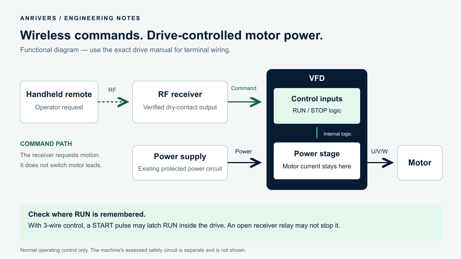
Control path and power path serve different jobs. This is a functional diagram, not a terminal wiring drawing. The speed reference must also be configured in the drive.
For terminal checks or changes, isolate the equipment and follow the drive's specified discharge and verification procedure. A stopped motor does not mean the drive is electrically isolated.
Find out where the RUN command is remembered
This is the question I would settle before discussing range or channel count.
Two-wire control: a maintained input state requests RUN. Removing that state requests a stop. The receiver must provide the intended maintained contact behavior.
Three-wire control: a START pulse can be remembered inside the drive. Releasing START does not cancel RUN; a separate STOP input clears it.
The names describe control arrangements, not how many conductors the whole installation needs. Terminal assignments and active states depend on the selected drive configuration. Schneider's two-wire and three-wire explanation illustrates this distinction.
For example, the ABB ACS355 manual describes a standard macro with level-operated start/stop and a separate three-wire macro for pushbuttons. Its digital-input common and input configuration also need to match the wiring. Copying the terminal numbers from a different drive is a poor shortcut.
Imagine a receiver delivering a short START pulse to a drive configured for three-wire control. The motor starts, the relay opens, and the motor continues running. That can be entirely correct behavior. Changing to a larger relay or a stronger transmitter will not change it.
Radio loss cannot press the STOP button for you
A separate wireless STOP button is useful for normal operation, but it still needs a working radio link. If the link disappears after a three-wire START pulse, no STOP pulse arrives. The drive may keep its stored RUN command.
Two-wire control does not solve this automatically either. If the receiver latches its RUN contact closed until another button press, radio silence may leave it closed. Check the receiver's actual output behavior; “momentary” and “toggle” labels are not a complete signal-loss specification.
Also check whether the radio system can detect link loss at all. Many simple remotes transmit only during a button press. Silence between presses is normal. A receiver cannot distinguish an idle transmitter from one that has disappeared without some form of ongoing link supervision.
Where loss of control must stop the process, specify the complete path: how the link is supervised, what output changes on timeout, which drive or controller input receives that change, and how a new start is permitted afterward. Verify it at the machine. Do not assume an unused NC relay terminal provides supervision; its power-off state and its RF-loss state may be different.
The ordinary RUN/STOP inputs discussed here provide operating control. Keep the machine's assessed emergency-stop and other safety functions in their designed safety circuit. A receiver's normal relay output does not become a safety function because it is connected to a drive.
The input is active, but the motor still does not turn
Once the drive's input monitor shows the expected change, stop treating every failure to move as an RF fault. Read the drive status.
Command source: is the drive accepting terminal commands, or does the keypad or fieldbus still own start/stop?
Input assignment: does that terminal mean RUN in the current macro, or has it been assigned another function?
Permissives and faults: is a normal stop, enable condition, fault, or safety state preventing operation? Diagnose the condition rather than bridging it out.
Speed reference: what speed is actually requested, and where is that value coming from?
A RUN request and a speed request are separate pieces of information. Selecting a preset speed may not start the motor; sending RUN may not produce useful motion if the active reference is zero. Schneider documents the separate run-command requirement for preset speeds. Confirm your drive's configuration rather than assuming one relay does both jobs.
Watch the input, the drive state, and the shaft separately
A useful commissioning record has three observations for each command: the receiver output state, the drive's interpreted command, and the machine response. A relay click proves only one part of that chain.
Use the drive's input and status monitors first. If the receiver changes but the input monitor does not, check the interface and common arrangement. If the input changes but the drive rejects RUN, check its configuration and permissives. If the drive accepts STOP but the motor takes time to settle, inspect the selected stopping method and the load's behavior.
Distinguish a controlled deceleration from coasting. Removing RUN does not guarantee an instant mechanical stop. A fan with inertia and a loaded conveyor can respond very differently to the same drive setting.
Test the awkward sequences before handing it over
With the machine secured for commissioning, test more than one successful START and STOP:
Release START after motion begins. Confirm whether continued running is intended.
Use the normal STOP command and record the actual stopping behavior.
Test the specified radio-loss response using an approved controlled method. Verify the drive and machine stop as intended, not merely that a receiver indicator changes.
Restore the radio link. Check whether a fresh start action is required.
Cycle receiver power separately from drive power. Repeat the agreed recovery checks after a drive fault reset and a local/remote handover.
Do not assume that calling a scheme “two-wire” or “three-wire” settles every restart condition. Record the relevant drive settings and the measured result. A maintenance technician should be able to reproduce the behavior without guessing which device remembered RUN.
Send the drive model with the remote-control enquiry
A useful starting brief is short: the exact drive model, its control-terminal page, the current command and reference sources, the required button functions, and the expected stop and restart behavior. Include whether the operator needs continuous supervision or only occasional start/stop commands.
That information decides the interface. Button count and radio range come afterward. The aim is a system whose response is predictable when the operator releases a button, loses the link, or comes back after a power interruption.
For related interface details, see dry contact versus powered receiver outputs. If variable speed is part of the job, see relay selection versus proportional speed control.