
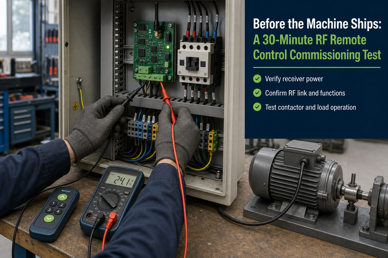
Short answer
Before a machine leaves the workshop, spend thirty minutes testing the RF remote as part of the complete control system—not as a transmitter and receiver sitting on a bench.
The test should cover the receiver supply, every button and output, the actual load, power-loss recovery, radio-loss behavior, worst-position range, interference from the machine, and replacement-transmitter procedure. Record the exact hardware and settings that passed. That short routine catches more field problems than another hour of checking the advertised range.
Do not start by walking away with the remote
The first thing people usually test is distance. They press a button, walk across the workshop, and stop when the relay no longer clicks. I used to do the same. It is quick, visible, and often the least useful test at that stage.
If the receiver supply drops when a contactor pulls in, the output mode is wrong, or the forward and reverse channels can operate together, the machine is not ready for a range test. Start at the receiver terminals and work outward. Radio comes after the electrical behavior is correct.
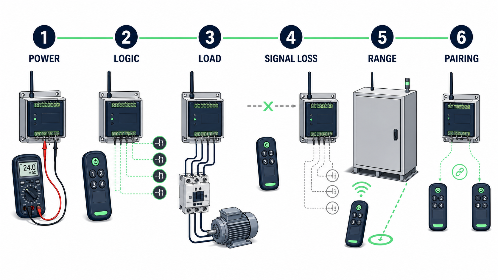
Commission in this order: power first, then logic and load behavior, followed by signal-loss, installed range, and pairing checks.
Freeze the configuration before testing
Write down what is actually fitted to the machine. Two samples that look identical can contain different receiver revisions, code formats, antennas, output settings, or transmitter batteries.
Transmitter model and hardware revision
Receiver model and hardware or firmware revision
Frequency and modulation
Coding or pairing method
Antenna type, length, and installation position
Receiver supply voltage
Output mode for each channel
Transmitter and receiver quantity in the approved set
This takes two minutes and prevents an awkward argument later about whether the production unit is the same as the sample that passed.
Check the receiver supply under the real load
Measure voltage directly across the receiver positive and negative terminals. Do not use the reading at the power supply as a substitute. Long wiring, shared returns, small conductors, and connector resistance can produce a very different voltage at the receiver.
Operate the largest motor, solenoid, lamp, brake, or contactor connected to the machine. Watch the receiver LED and use the meter’s min/max function if available. A short dip may reset the receiver even though the normal reading looks perfect.
I also switch the load off repeatedly. The troublesome event is often the inductive spike when current is interrupted, not the current drawn while the load is running. If a receiver resets, triggers an extra output, or loses its learned code during this test, fix the supply and suppression before changing the antenna.
Verify every button against the written function
Do not accept “all four channels work.” Check what each button is supposed to do and what every output actually does.
Momentary: The output follows the button and releases when the button is released.
Toggle: One press turns the output on and the next press turns it off.
Set and reset: Separate commands produce a defined on and off state.
Interlocked: Opposing outputs cannot remain active together.
Test short presses, long presses, and quick changes between buttons. For a reversing motor, press forward and reverse in the least polite sequence an operator might use. Hold one direction and press the other. Release both and press again immediately. The logic should remain predictable without relying on careful timing from the operator.
Check the machine motion, not only the receiver LEDs. A swapped relay wire can make every indicator look correct while the equipment moves in the wrong direction.
Test power loss before it happens in the field
With the machine in each relevant operating state, remove and restore receiver power. Then repeat the test by switching off the complete control panel.
The questions are simple:
Do all outputs return off, or does the receiver restore the previous state?
Can a motor, heater, valve, or lamp restart without a new command?
Does the receiver reconnect to the correct transmitter?
Is the learned memory retained after a short interruption and a long interruption?
Does a slow supply ramp produce different behavior from a clean switch-on?
A toggle output that remembers its state may be convenient for lighting and unacceptable for moving equipment. Decide the required restart behavior from the application, then verify it on the finished machine.
Test lost-signal behavior while a command is active
For a momentary or hold-to-run function, keep the command active and remove the radio link. Depending on the system, this can be tested by moving out of range, shielding the transmitter, removing its battery, or switching off transmitter power.
Measure how long the output remains active. Some receivers release as soon as valid packets stop. Others stay on until an internal timeout expires. A basic latching receiver may remain in its previous state indefinitely.
There is no universal correct timeout. A gate light, hydraulic valve, winch, and ventilation fan have different requirements. What matters is that the behavior is specified, measured, and accepted before shipment. Emergency-stop and other safety functions still require an independent safety architecture; a normal RF timeout does not replace it.
Switch the real load during the range test
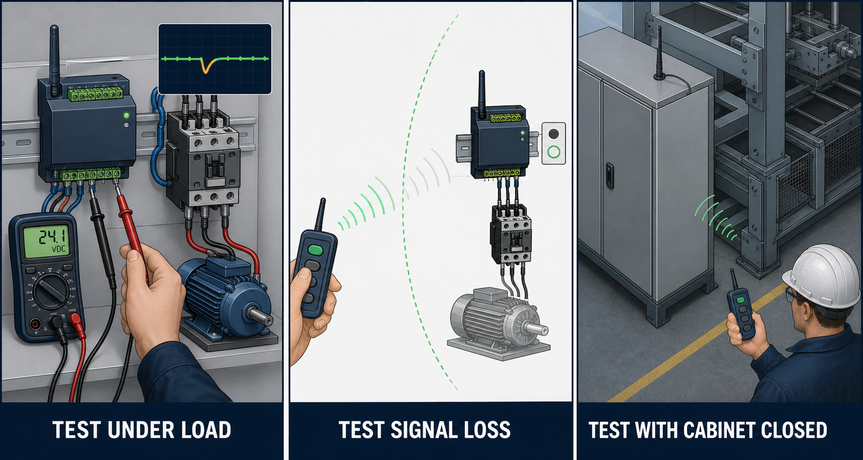
These three conditions expose many faults that remain hidden during a quiet open-bench test.
Once the electrical tests pass, close the cabinet, fit the covers, route the antenna as it will be delivered, and operate the actual load. Range measured with an open metal door and a quiet machine is not the installed range.
Test from the worst useful operator positions:
behind the machine rather than only in front of the receiver;
close to steel structures, vehicles, racks, or reinforced walls;
with the transmitter held naturally, including with gloves if that is normal use;
while motors, contactors, inverters, LED drivers, or solenoids are switching;
with the cabinet door closed and the final antenna orientation fixed;
with a transmitter battery near its replacement threshold, not only a new battery.
I want repeatable operation beyond the required working boundary, not one successful press at the maximum possible distance. Walk the area several times and operate every important command. A single dead spot near the normal operating position matters more than an impressive open-field result in the opposite direction.
Check pairing, memory, and the replacement procedure
Pair the number of transmitters the customer will actually use. Confirm that each one controls the correct receiver and that a transmitter from another machine cannot operate it.
Then perform the service procedure once:
Remove one learned transmitter from the receiver memory.
Confirm that the removed transmitter no longer works.
Add a replacement transmitter.
Check that the remaining authorized transmitters still work.
Power-cycle the receiver and verify the memory again.
If the receiver only supports a complete memory erase, say so in the service instructions. Discovering that limitation after one remote is lost usually leads to confusion on site.
Inspect the transmitter like a tool, not a sample
The transmitter will be dropped, carried in a pocket, used with dirty hands, and sometimes left in a vehicle. Check the details that are easy to ignore during an electrical test.
Buttons return cleanly and do not stick at the edges.
Labels match the actual machine direction and remain readable.
The battery cover and key ring cannot loosen during normal handling.
The enclosure closes correctly after the battery is replaced.
The indicator behavior for transmission and low battery is understood.
Spare transmitters have the same frequency, coding method, and button mapping.
If the remote will be used in rain, cold, oil, dust, or with gloves, a desk test is not enough. At minimum, operate the approved sample in the expected handling condition before production is released.
A practical 30-minute sequence
When time is tight, this is the order I use:
Five minutes: Record the transmitter, receiver, frequency, antenna, supply, and output settings.
Five minutes: Check every button, output mode, direction, limit, and interlock.
Five minutes: Measure receiver voltage while the largest loads start and stop repeatedly.
Five minutes: Test receiver power loss, transmitter power loss, lost signal, and restart behavior.
Five minutes: Test range from the worst working positions with the machine operating and covers closed.
Five minutes: Verify all paired transmitters, remove and add one remote, then photograph labels and record the approved result.
A complex machine may need a longer validation plan, but this half-hour test is a sensible minimum for a normal RF control function. It gives production, service, and the customer a common reference.
Failures this test should catch before shipment
The relay clicks but the motor does not move: Check the output interface, common terminal, contact rating, driver stage, and field wiring.
The receiver resets when a load switches: Check voltage dip, shared return wiring, inductive suppression, and conducted noise.
Forward and reverse can energize together: Correct the receiver logic and add the required electrical or mechanical interlock.
Range is good with the cabinet open and poor when closed: Move the antenna outside the metal enclosure or provide an RF-transparent antenna area.
The output remains active after the transmitter disappears: Confirm whether the receiver provides a supervised timeout and whether that behavior suits the application.
A replacement remote erases all existing remotes: Document the memory procedure and make sure the customer has a workable service plan.
The practical conclusion
An RF remote control should be commissioned as part of the machine. The receiver supply, load, control logic, enclosure, antenna, interference environment, and operator position all affect the result.
The fastest way I know to reduce field calls is to test the ugly moments before shipment: the motor starting, the contactor releasing, the cabinet door closing, the transmitter battery weakening, the link disappearing, and the power returning. When the system behaves correctly through those events, the range test finally means something.
Keep the test record with the machine serial number. Six months later, that page is often more useful than the receiver brochure.